430.000.000+ O-rings in stock
Fast delivery
Static axial compression of an O-ring works differently from radial compression: the ring is not compressed radially, but axially squeezed between two flat opposing surfaces. Think of a lid being tightened onto a housing, or two flanges being bolted together. Where the ring must sit in the groove and how much it is compressed depends entirely on the direction of the pressure. With internal pressure, the ring belongs on the outside of the groove; with external pressure, on the inside. This distinction is decisive for the entire groove geometry and is regularly overlooked in practice.
In static axial compression, the cross-section of the O-ring is compressed in the axial direction, perpendicular to the central axis of the ring. Think of a lid tightened onto a housing, or a flange bolted onto a mating flange. The ring sits in an annular groove in one of the flat mating faces. There is no relative movement: the ring only has to hold under pressure. Even so, there is one critical point that goes wrong more often in static axial applications than in radial ones: the pressure direction. Whether the overpressure is on the inside or on the outside of the construction determines on which side of the groove the ring must bear. If you position the ring on the wrong side, the pressure will push it away from the sealing surface instead.
This is the most critical point in axial applications. There are exactly two situations, and the groove geometry is the same for both. What differs is where the ring must sit in the groove and how much compression or expansion occurs. If you use the wrong setup for your pressure direction, the pressure actively works against the seal and the system will leak at the first pressure build-up. Always check the pressure direction before assembly.
The O-ring must lie against the outside diameter of the groove. The internal pressure pushes the ring outward, and the outer groove wall absorbs that force. In this scenario, the ring is compressed in the axial direction by approximately 1% to a maximum of 3%. This is deliberately limited: the pressure helps the sealing effect, so high assembly preload is not required.
The O-ring must lie against the inside diameter of the groove. The external pressure forces the ring inward. Here, the ring may expand slightly, up to a maximum of 6% of the cross-section diameter. Note: this is not compression but expansion. Six percent is a hard upper limit. Above that, the strain in the rubber increases to the point where fatigue cracks develop, especially during long-term use or at high temperatures.
Rule of thumb: internal pressure = ring outward, 1-3% compression. External pressure = ring inward, max. 6% expansion.
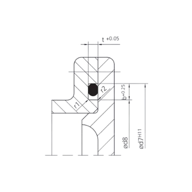
The groove for axial compression has fewer parameters than the radial groove: there is no chamfer length z, because the ring is not placed over a sharp edge during assembly. The ring is simply laid into the flat groove. Five parameters define the groove completely: cross-section diameter (d2), groove depth (t), groove width (b), and the two corner radii (r1 and r2). All five depend directly on d2.
The starting point for the entire groove calculation. In axial compression, the common cross-section diameters are the same as in radial applications: 1.78 mm, 2.62 mm, 3.53 mm and 5.33 mm for standard constructions. The cross-section diameter determines how much rubber is present in the groove and therefore directly affects the contact force on the sealing surface. Always use the ring for which the groove has been dimensioned.
The groove depth is slightly smaller than the cross-section diameter, so that the ring protrudes slightly above the surface and is compressed during assembly. The tolerance is only positive: the groove may be slightly deeper, but never shallower. A groove that is too shallow creates too much compression and may damage the ring or the mating surface. A groove that is too deep creates too little preload and will already leak at low pressure.
The groove width determines how much space the ring has to deform in the axial direction when the faces are pulled together. In axial compression, the width is calculated more generously than in radial compression, because in this case the rubber flows in the radial direction. Too narrow causes excessive lateral stress. Too wide creates room for the rubber to roll, which leads to uneven sealing.
The base radius r1 increases from 0.3 mm for small cross-section diameters to 1.5 mm at d2 = 15 mm. r2 remains constant at 0.2 mm for almost all sizes. Sharp radii create local stress concentrations in the rubber, especially at higher operating pressures or under pulsating loads. Always apply the radii exactly as indicated in the table.
The sealing faces in axial applications are usually flat, turned or milled surfaces. These are relatively easy to machine to the required roughness, but in practice they are still too often treated as construction surfaces rather than sealing surfaces. The roughness requirement for the sealing surface in static applications is Ra max. 1.6 µm (Rz max. 6.3 µm). The groove base may be Ra max. 3.2 µm. One turning groove or a scratch in the radial direction across the sealing surface is enough to create a continuous leak path along the O-ring. Always clean the surfaces before assembly and inspect them visually for scratches, burrs or machining marks. If in doubt, rework them.
Axial applications have a different category of mistakes than radial ones. There are no sharp edges at the lead-in side, so damage during assembly is less of a risk. The mistakes we see are almost always related to the pressure direction or the groove geometry.
The groove geometry is material-independent and applies equally to NBR, EPDM and FKM. What differs per material is its suitability for the medium, the operating temperature and long-term stability under pressure. NBR is the standard choice for hydraulic and mechanical applications up to +100 °C. EPDM is used for water, steam and outdoor applications. FKM is resistant to aggressive chemicals and temperatures up to +200 °C. Under pulsating or cyclic loads, the fatigue resistance of the material also plays a role.
Check the compatibility of your medium via the chemical resistance guide on o-ring-stocks.eu.
| d2 | t | b | r1 |
| 0.5 | 0.35 | 0.7 | 0.3 |
| 0.74 | 0.5 | 1.1 | 0.3 |
| 1 | 0.7 | 1.4 | 0.3 |
| 1.02 | 0.75 | 1.4 | 0.3 |
| 1.2 | 0.85 | 1.7 | 0.3 |
| 1.25 | 0.9 | 1.7 | 0.3 |
| 1.27 | 0.9 | 1.8 | 0.3 |
| 1.3 | 0.95 | 1.8 | 0.3 |
| 1.42 | 1.05 | 1.9 | 0.3 |
| 1.5 | 1.1 | 2.1 | 0.3 |
| 1.52 | 1.1 | 2.1 | 0.3 |
| 1.6 | 1.2 | 2.2 | 0.3 |
| 1.63 | 1.2 | 2.2 | 0.3 |
| 1.78 | 1.3 | 2.6 | 0.3 |
| 1.8 | 1.3 | 2.6 | 0.3 |
| 1.83 | 1.35 | 2.6 | 0.3 |
| 1.9 | 1.4 | 2.7 | 0.3 |
| 1.98 | 1.5 | 2.8 | 0.3 |
| 2 | 1.5 | 2.8 | 0.3 |
| 2.08 | 1.55 | 2.9 | 0.3 |
| 2.1 | 1.55 | 2.9 | 0.3 |
| 2.2 | 1.6 | 3.1 | 0.3 |
| 2.26 | 1.7 | 3.1 | 0.3 |
| 2.3 | 1.75 | 3.1 | 0.3 |
| 2.34 | 1.75 | 3.1 | 0.3 |
| 2.4 | 1.8 | 3.3 | 0.3 |
| 2.46 | 1.85 | 3.4 | 0.3 |
| 2.5 | 1.9 | 3.4 | 0.3 |
| 2.6 | 2 | 3.5 | 0.3 |
| 2.62 | 2 | 3.6 | 0.3 |
| 2.65 | 2 | 3.7 | 0.3 |
| 2.7 | 2.05 | 3.7 | 0.3 |
| 2.8 | 2.1 | 3.9 | 0.3 |
| 2.92 | 2.2 | 4 | 0.3 |
| 2.95 | 2.2 | 4 | 0.3 |
| 3 | 2.3 | 4 | 0.3 |
| 3.1 | 2.4 | 4.1 | 0.6 |
| 3.5 | 2.7 | 4.8 | 0.6 |
| 3.53 | 2.7 | 4.8 | 0.6 |
| 3.55 | 2.7 | 4.9 | 0.6 |
| 3.6 | 2.8 | 5 | 0.6 |
| 3.7 | 2.9 | 5.1 | 0.6 |
| 4 | 3.1 | 5.4 | 0.6 |
| 4.3 | 3.4 | 5.8 | 0.6 |
| 4.5 | 3.5 | 6 | 0.6 |
| 5 | 4 | 6.6 | 0.6 |
| 5.3 | 4.3 | 7.1 | 0.6 |
| 5.33 | 4.3 | 7.1 | 0.6 |
| 5.5 | 4.4 | 7.4 | 0.6 |
| 5.7 | 4.6 | 7.5 | 0.6 |
| 6 | 4.9 | 7.8 | 0.6 |
| 6.5 | 5.3 | 8.5 | 1 |
| 6.99 | 5.7 | 9.6 | 1 |
| 7 | 5.7 | 9.6 | 1 |
| 7.5 | 6.2 | 10.1 | 1 |
| 8 | 6.6 | 10.7 | 1 |
| 8.4 | 7 | 11.1 | 1 |
| 8.5 | 7.1 | 11.3 | 1 |
| 9 | 7.6 | 11.8 | 1 |
| 9.5 | 8.1 | 12.4 | 1 |
| 10 | 8.5 | 13.1 | 1 |
| 10.5 | 8.9 | 13.7 | 1 |
| 11 | 9.4 | 14.3 | 1 |
| 11.5 | 9.9 | 14.8 | 1 |
| 12 | 10.4 | 15.4 | 1 |
| 12.5 | 10.8 | 16 | 1.5 |
| 13 | 11.3 | 16.6 | 1.5 |
| 13.5 | 11.8 | 17.2 | 1.5 |
| 14 | 12.2 | 17.8 | 1.5 |
| 14.5 | 12.7 | 18.4 | 1.5 |
| 15 | 13.2 | 19.1 | 1.5 |
In radial compression, the ring is compressed between two cylindrical surfaces, perpendicular to the axis. In axial compression, the ring is compressed between two flat mating surfaces, in the direction of the axis. Axial compression is used for lids, flanges and flat connections.
With internal overpressure: approximately 1% up to a maximum of 3%. With external pressure, the ring may expand slightly, up to a maximum of 6%. Outside these limits, fatigue or permanent deformation occurs.
No. In axial assembly, the O-ring is placed in a flat groove, not slid over an edge. Chamfers are therefore not required and are not included in the size table for axial compression.
Yes, the ring itself is the same. Only the groove differs. The groove depth, groove width and radii are dimensioned differently for axial applications than for radial ones. Always use the table that belongs to the installation type.
For high pressures and aggressive media, FKM (Viton) is the preferred choice because of its high chemical resistance and mechanical stability. For standard applications, NBR is sufficient. Consult the chemical resistance guide for your specific medium.

 Nederlands
  Deutsch
  Français
  Italiano
  Español