In several applications, such as a secondary seal in a floating ring seal of a nuclear power plant's feed water pump or as a seal at a temporary screw-in connection for automobile air conditioning systems, the O-ring has shown to be an effective and affordable sealing element. These are only a few of the numerous instances when O-rings have fulfilled the strictest standards for leak tightness, regardless of the medium or temperature—from -60 °C to 300 °C. O-rings are simply mounted, widely accessible, and just need a basic seal housing. Because of this, design engineers find it particularly frustrating when O-rings must be rejected as sealing components in order to solve an issue because of excessive measurement deviation. It will often cost the consumer extra to rely on other sealing.
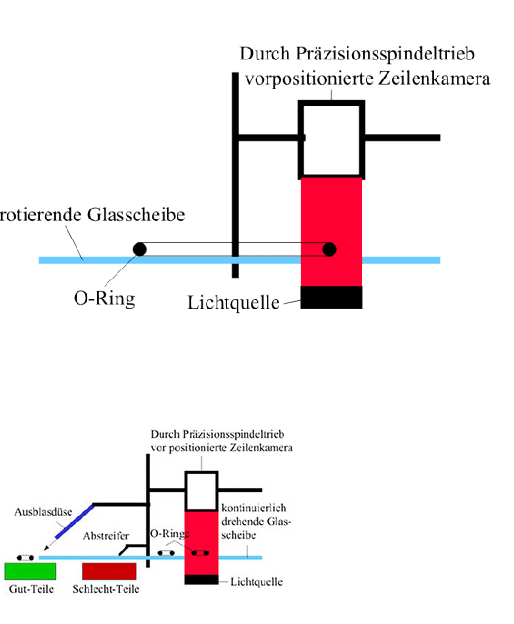
Especially for smaller O-ring applications, the DIN 3771 part 1 common tolerances provide a significant limitation on their applicability. This study illustrates the causes behind the manufacturing process variations in O-ring measurements and the functional consequences that follow. It outlines a brand-new, very accurate optical measuring method for O-rings that is being resold as a service for precise tolerance-based measurement and sorting.
Due mostly to the production process, there are three determining factors:
-Variations in mold temperature when O-rings are curing
-Variations in rubber's and other chemical components' shrinking behavior
-Mold offset as a result of the guide bolt's diameter clearance increasing with running time owing to wear.
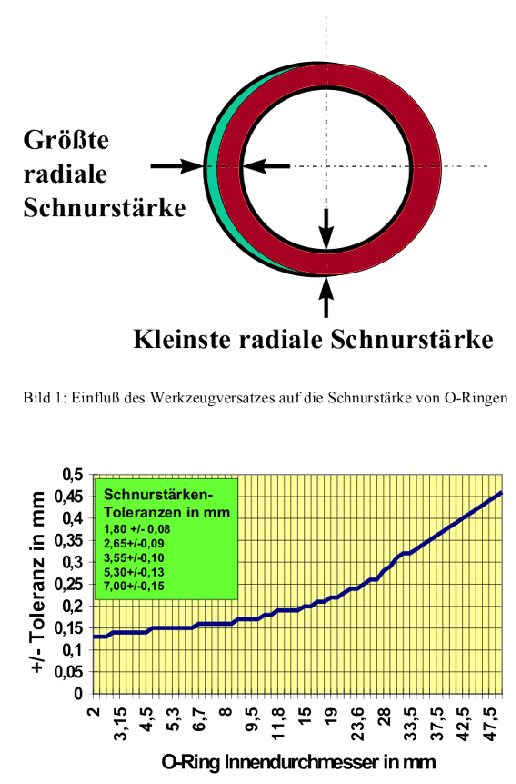
Temperature variations can cause significant differences in diameter measurements even within a single batch, particularly when large molds are used to create O-rings. Batch-related variations in compound composition and modest batch-related temperature variations can cause clearly visible changes in inner diameters even in highly temperature-controlled procedures, such as those that can be achieved with tiny injection molds. Another crucial influencing element for the cable thickness, an O-ring's functional dimension that is normally more significant, is the mould offset. Figure 1 uses a straightforward top view of an O-ring (upper mould half = red, bottom mould half = turquoise) to show how variations in cord thickness can happen on an O-ring as a result of the offset of the higher and lower halves. DIN 3771 part 4 states that although this offset is often less than 0.05 mm on fresh injection molds, wear can cause it to greatly rise, adding up to 0.05 to 0.1 mm.

 Nederlands
  Deutsch
  Français
  Italiano