430.000.000+ O-rings in stock
Fast delivery
Static radial compression with an O-ring seems simple: ring in the groove, lid on, done. Yet most leakage problems are in the groove itself. Milled too deep, no chamfer on the lead-in side, or a tolerance that falls just outside the permitted range: it is enough to cause the seal to fail, sometimes immediately, sometimes only after a few operating hours. This article covers all six groove parameters for static radial compression with an O-ring, including the full size table and the most common mistakes in practice.
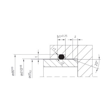
The groove for static radial sealing is defined by six parameters. Together, they determine how much the O-ring is compressed, whether it remains intact during assembly, and whether the rubber can deform freely enough. If one of these dimensions is incorrect, that is usually enough to cause a leak, sometimes visible immediately, sometimes only after hours or days of use. The parameters are cross-section diameter (d2), groove depth (t), groove width (b1), lead-in chamfer length (z) and two corner radii (r1 and r2). They all depend directly on d2: the cross-section diameter is the starting point for the entire calculation. The standard table takes that calculation work off your hands, but understanding what each parameter does helps you identify errors before assembly, not only afterwards.
The cross-section diameter is the starting point for the entire groove calculation. Groove depth, groove width, chamfer length and the two radii are all derived from d2. If you choose an O-ring with a different cross-section diameter than the groove was designed for, all the other dimensions will no longer be correct. Common cross-section diameters for static radial applications are 1.78 mm, 2.62 mm, 3.53 mm and 5.33 mm. These are the AS568 and ISO 3601 standard sizes that fit the vast majority of designs.
The groove depth is always smaller than the cross-section diameter. The difference determines the compression: how firmly the O-ring is pressed against the mating surface. Too much compression will damage the rubber over time. Too little and the contact pressure is insufficient. The recommended range is between 15 and 30% of d2.
Compression (%) = (d2 − t) / d2 × 100. With d2 = 3.00 mm and t = 2.30 mm: 23%.
The tolerance on t is only positive (+0.05 mm): the groove may be slightly deeper than the nominal dimension, but never shallower. Always check the t dimension with a depth gauge, even if the tool still looks new.
When an O-ring is compressed radially, the rubber flows in the axial direction. The groove must be wide enough to accommodate that deformation, otherwise the ring becomes distorted and loses its round cross-section. A ring that is no longer round causes irregular contact pressure around the circumference, and that almost always leads to leakage. The tolerance on b1 is +0.25 mm: slightly wider is allowed, narrower is not. When in doubt, choose the wider dimension.
The most frequently overlooked parameter in the entire design. Without a chamfer on the lead-in side, the O-ring slides over a sharp edge during assembly. After assembly the ring appears completely intact, but it has internal microscopic cracks. These become visible when the seal is pressurized, sometimes immediately, sometimes only after several operating hours. The recommended angle is 15 to 20 degrees. The z value increases with the cross-section diameter: from 1.5 mm at d2 = 1.78 mm to 6.0 mm at d2 = 15.00 mm.
The base radius r1 prevents stress concentrations in the rubber at the point where the ring touches the groove base. For small cross-section diameters (up to d2 = 3.00 mm), r1 = 0.3 mm applies. Above d2 = 3.10 mm, r1 increases to 0.6 mm, and above d2 = 6.50 mm to 1.0 mm or more. The corner radius r2, at the top of the groove, remains almost constant at 0.2 mm. A radius that is too small creates additional stress in the rubber at higher operating pressures.
The groove is correct, the tolerances have been observed, the ring is installed properly, yet the seal still leaks. That is a pattern we encounter regularly. Almost always, the cause lies in two factors that fall outside the groove geometry: the roughness of the sealing surface and the width of the gap between the two components. One turning groove or scratch in the sealing surface is enough to create a continuous leak path along the O-ring, especially at low operating pressures where the ring presses less firmly. A gap that is too wide leads to extrusion at higher pressures: the rubber is forced into the opening and is then irreversibly damaged. Both factors can be controlled well with the right surface treatment and dimensioning.
Roughness values: sealing surface Ra max. 1.6 µm (Rz max. 6.3 µm), groove base Ra max. 3.2 µm, groove flanks Ra max. 6.3 µm. One turning groove is enough to create a leak path.
Gap width at 70 Shore A: up to 63 bar max. 0.2 mm; at 100–160 bar max. 0.05 mm; above 100 bar back-up rings recommended.
Silicone: halve the permitted gap width. Silicone has a lower tensile strength than NBR or FKM.
Technical leakage problems rarely have a mysterious cause. In practice, three mistakes keep recurring, regardless of the industry or type of application. What they have in common is that they are not visible during visual inspection after assembly: the groove looks fine, the ring is seated correctly, but the system leaks as soon as it is pressurized. Or worse: it only starts leaking after a few operating hours, when someone has long since assumed everything was fine. All three mistakes below are preventable. They require no extra material, no more expensive tools and no design modification, only an extra check at the right moment in the assembly process.
The groove geometry and the size table are material-independent: the same dimensions apply to NBR, EPDM and FKM. What does differ per material is its suitability for the medium and the operating temperature. The wrong material choice leads to swelling, shrinkage or chemical degradation of the ring, even if the groove and the compression are exactly correct. NBR is the standard choice for most hydraulic and pneumatic applications. EPDM performs better with water and steam. FKM (Viton) is resistant to aggressive chemicals and high temperatures. Below -30 °C or above +100 °C, additional material requirements apply that fall outside the standard tables. If in doubt, consult the chemical resistance guide or contact our specialists.
Check compatibility with your medium via the chemical resistance guide (1,500+ media).
|
(d2) |
(t) +0,05 |
(b1) +0,25 |
(r1) |
| 0,5 | 0,35 | 0,7 | 0,3 |
| 0,74 | 0,5 | 1,1 | 0,3 |
| 1 | 0,7 | 1,4 | 0,3 |
| 1,02 | 0,7 | 1,4 | 0,3 |
| 1,2 | 0,85 | 1,7 | 0,3 |
| 1,25 | 0,9 | 1,7 | 0,3 |
| 1,27 | 0,9 | 1,7 | 0,3 |
| 1,3 | 0,95 | 1,8 | 0,3 |
| 1,42 | 1,05 | 1,9 | 0,3 |
| 1,5 | 1,1 | 2 | 0,3 |
| 1,52 | 1,1 | 2 | 0,3 |
| 1,6 | 1,2 | 2,2 | 0,3 |
| 1,63 | 1,2 | 2,2 | 0,3 |
| 1,78 | 1,3 | 2,4 | 0,3 |
| 1,8 | 1,3 | 2,4 | 0,3 |
| 1,83 | 1,35 | 2,5 | 0,3 |
| 1,9 | 1,4 | 2,6 | 0,3 |
| 1,98 | 1,5 | 2,7 | 0,3 |
| 2 | 1,5 | 2,7 | 0,3 |
| 2,08 | 1,55 | 2,8 | 0,3 |
| 2,1 | 1,55 | 2,8 | 0,3 |
| 2,2 | 1,65 | 3 | 0,3 |
| 2,26 | 1,7 | 3 | 0,3 |
| 2,3 | 1,75 | 3 | 0,3 |
| 2,34 | 1,75 | 3,1 | 0,3 |
| 2,4 | 1,8 | 3,2 | 0,3 |
| 2,46 | 1,85 | 3,3 | 0,3 |
| 2,5 | 1,9 | 3,3 | 0,3 |
| 2,6 | 2 | 3,5 | 0,3 |
| 2,62 | 2 | 3,5 | 0,3 |
| 2,65 | 2 | 3,6 | 0,3 |
| 2,7 | 2,05 | 3,6 | 0,3 |
| 2,8 | 2,15 | 3,7 | 0,3 |
| 2,92 | 2,2 | 3,9 | 0,3 |
| 2,95 | 2,2 | 3,9 | 0,3 |
| 3 | 2,3 | 4 | 0,3 |
| 3,1 | 2,4 | 4,1 | 0,6 |
| 3,5 | 2,7 | 4,6 | 0,6 |
| 3,53 | 2,7 | 4,7 | 0,6 |
| 3,55 | 2,7 | 4,7 | 0,6 |
| 3,6 | 2,8 | 4,8 | 0,6 |
| 3,7 | 2,9 | 4,9 | 0,6 |
| 4 | 3,1 | 5,3 | 0,6 |
| 4,3 | 3,4 | 5,6 | 0,6 |
| 4,5 | 3,5 | 5,9 | 0,6 |
| 5 | 4 | 6,6 | 0,6 |
| 5,3 | 4,3 | 7 | 0,6 |
| 5,33 | 4,3 | 7 | 0,6 |
| 5,5 | 4,4 | 7,2 | 0,6 |
| 5,7 | 4,6 | 7,5 | 0,6 |
| 6 | 4,9 | 7,8 | 0,6 |
| 6,5 | 5,3 | 8,5 | 1 |
| 6,99 | 5,8 | 9,2 | 1 |
| 7 | 5,8 | 9,2 | 1 |
| 7,5 | 6,2 | 9,9 | 1 |
| 8 | 6,7 | 10,5 | 1 |
| 8,4 | 7 | 11 | 1 |
| 8,5 | 7,1 | 11,2 | 1 |
| 9 | 7,6 | 11,8 | 1 |
| 9,5 | 8,1 | 12,4 | 1 |
| 10 | 8,5 | 13 | 1 |
| 10,5 | 9 | 13,6 | 1 |
| 11 | 9,5 | 14,2 | 1 |
| 11,5 | 9,9 | 14,8 | 1 |
| 12 | 10,4 | 15,4 | 1 |
| 12,5 | 10,8 | 16 | 1,5 |
| 13 | 11,3 | 16,6 | 1,5 |
| 13,5 | 11,8 | 17,2 | 1,5 |
| 14 | 12,2 | 17,8 | 1,5 |
| 14,5 | 12,7 | 18,4 | 1,5 |
| 15 | 13,2 | 19,1 | 1,5 |
15 to 30% of the cross-section diameter. Formula: (d2 - t) / d2 × 100. The dimensions in the standard table always fall within this range.
During assembly, the ring develops microscopic internal cracks. These only become visible under pressure, sometimes only after hours or days. A chamfer of 15–20 degrees prevents this.
Above 63 bar at 70 Shore A. At higher hardness levels, the limit is slightly higher. Silicone always requires narrower gaps than NBR or FKM.
The groove geometry is identical. Only the maximum gap width must be halved, because silicone has a lower tensile strength and extrudes more quickly.
NBR for oil and water, EPDM for steam and outdoor applications, FKM for chemicals up to +200 °C. Consult the chemical resistance guide for your specific medium.

 Nederlands
  Deutsch
  Français
  Italiano
  Español