430.000.000+ O-rings in stock
Fast delivery


 Nederlands
  Deutsch
  Français
  Italiano
  Español
The triangular O-ring groove is the exception. For O-ring sealing, we always recommend a rectangular groove, because it is easier to machine and offers more tolerance for small dimensional deviations. But in lids or flanges, it may be necessary for design reasons to use a triangular O-ring groove, for example if there is insufficient material depth for a full rectangular groove. In that case, different parameters, fewer degrees of freedom and tighter tolerances apply. Use it only if the design truly requires it.
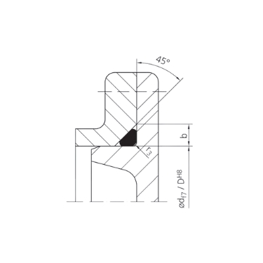
A triangular groove, also called a V-groove, has a triangular cross-section instead of the usual rectangular shape. The groove tapers toward the bottom. When the two parts are joined, the O-ring is pressed into the corner of the triangle and the contact takes on a special geometry. In practice, the triangular groove is used almost exclusively for face seals, such as lids on housings or flanges on drain openings. Its applicability is therefore narrower than that of the rectangular groove. The reason manufacturers still choose this groove shape is almost always structural: there is insufficient depth for a full rectangular groove, or the geometry of the part makes a rectangular groove difficult to mill. Never use the triangular groove by preference, only when the design truly requires it.
The triangular groove is a fallback solution with a clearly defined range of application. Outside that range, the rectangular groove is always the better choice: easier to mill, more tolerant of dimensional deviations and better able to withstand variations in assembly force. If you still choose the triangular groove, the tolerances must be respected. This is a design with little margin.
The triangular groove has only three parameters: cross-section diameter (d2), groove width (b) and base radius (r3). There is no separate groove depth t in the table, because in a triangular groove the depth follows directly from the groove width and the groove angle. The tolerance on b is only positive and increases with the cross-section diameter. That is the only free element in the design: slightly wider is allowed, narrower is not.
The cross-section diameter is also the starting point here. The triangular groove is available for cross-section diameters from 1.50 mm to 15.00 mm. The width b and the base radius r3 are derived directly from d2. Always use the ring for which the groove was designed: a different cross-section diameter completely changes the contact geometry and results in an unreliable seal.
The groove width is the only parameter shown directly in the table for the triangular groove. The tolerance varies per cross-section diameter: +0.1 mm for small sizes (d2 up to 1.80 mm), increasing to +0.4 mm for larger sizes (d2 above 8.40 mm). Note: this tolerance is asymmetrical and only positive. A groove that is too narrow causes excessive deformation of the ring. A groove that is too wide results in insufficient contact pressure.
The base radius r3 increases from 0.3 mm for small cross-section diameters to 3.0 mm at d2 = 15.00 mm. This is a significantly larger radius than in rectangular grooves. The reason is the contact geometry: in a triangular groove, the ring rests on the sloping flanks, and the bottom serves as a guide surface. A base that is too sharp creates point loading in the rubber, which leads to premature damage.
The triangular groove places higher demands on machining accuracy than the rectangular groove. The angle of the groove walls must be correct: a deviating angle creates an asymmetrical contact zone on the O-ring and therefore uneven sealing around the circumference. After machining, always check the angle of the groove flanks, the base radius and the width b. Burrs at the transition from the groove flank to the sealing surface are a direct risk to the ring during assembly.
Sealing surface finish: Ra max. 1.6 µm (Rz max. 6.3 µm). This applies to the flat sealing surface outside the groove.
Groove base: Ra max. 3.2 µm. The bottom of the V-groove may be slightly rougher.
Groove flanks: Ra max. 6.3 µm. The sloping flanks are the least critical in terms of roughness.
The material choice for the triangular groove is the same as for other static applications: NBR for standard media, EPDM for water and steam, FKM for aggressive chemicals up to +200 °C. Keep in mind that the contact zone in a triangular groove is narrower than in a rectangular groove. At higher operating pressures, the contact pressure on the rubber is therefore higher, which makes the material requirements slightly more demanding.
Consult the chemical resistance guide for compatibility with your specific medium.
| d2 | b | Tol. | r3 |
| 1,50 | 2,05 | +0,1 | 0,3 |
| 1,60 | 2,20 | +0,1 | 0,3 |
| 1,78 | 2,40 | +0,1 | 0,3 |
| 1,80 | 2,40 | +0,1 | 0,3 |
| 1,90 | 2,60 | +0,1 | 0,4 |
| 2,00 | 2,70 | +0,1 | 0,4 |
| 2,20 | 3,00 | +0,1 | 0,4 |
| 2,40 | 3,20 | +0,15 | 0,4 |
| 2,50 | 3,40 | +0,15 | 0,5 |
| 2,60 | 3,60 | +0,15 | 0,5 |
| 2,62 | 3,60 | +0,15 | 0,5 |
| 2,65 | 3,60 | +0,15 | 0,5 |
| 2,70 | 3,70 | +0,15 | 0,6 |
| 2,80 | 3,80 | +0,15 | 0,6 |
| 3,00 | 4,10 | +0,2 | 0,6 |
| 3,10 | 4,20 | +0,2 | 0,6 |
| 3,50 | 4,80 | +0,2 | 0,8 |
| 3,53 | 4,80 | +0,2 | 0,8 |
| 3,55 | 4,80 | +0,2 | 0,8 |
| 3,60 | 4,90 | +0,2 | 0,9 |
| 3,70 | 5,00 | +0,2 | 0,9 |
| 4,00 | 5,50 | +0,2 | 1,2 |
| 4,30 | 5,90 | +0,2 | 1,2 |
| 4,50 | 6,20 | +0,2 | 1,2 |
| 5,00 | 6,80 | +0,25 | 1,2 |
| 5,30 | 7,20 | +0,25 | 1,4 |
| 5,33 | 7,30 | +0,25 | 1,4 |
| 5,50 | 7,50 | +0,25 | 1,5 |
| 5,70 | 7,80 | +0,25 | 1,5 |
| 6,00 | 8,20 | +0,3 | 1,5 |
| 6,50 | 8,80 | +0,3 | 1,7 |
| 6,99 | 9,60 | +0,3 | 2,0 |
| 7,00 | 9,60 | +0,3 | 2,0 |
| 7,50 | 10,20 | +0,3 | 2,0 |
| 8,00 | 10,90 | +0,3 | 2,0 |
| 8,40 | 11,40 | +0,3 | 2,0 |
| 8,50 | 11,60 | +0,4 | 2,0 |
| 9,00 | 12,50 | +0,4 | 2,5 |
| 9,50 | 13,10 | +0,4 | 2,5 |
| 10,00 | 13,70 | +0,4 | 2,5 |
| 10,50 | 14,30 | +0,4 | 2,5 |
| 11,00 | 15,00 | +0,4 | 2,5 |
| 12,00 | 16,50 | +0,4 | 3,0 |
| 15,00 | 20,40 | +0,4 | 3,0 |
Only if a rectangular groove is not structurally feasible, for example because of insufficient material depth or in an existing part where milling would create a structural objection. In all other cases, the rectangular groove is the better choice.
When executed correctly, the sealing performance is comparable. But the triangular groove has less tolerance for dimensional deviations and places higher demands on machining accuracy. The risk of errors is greater.
The standard table runs from d2 = 1.50 mm to d2 = 15.00 mm. Outside that range, no standardized dimensions are available.
For the rectangular groove, the tolerance on groove width b1 is a fixed +0.25 mm. For the triangular groove, the tolerance varies per cross-section diameter, from +0.1 mm for small sizes up to +0.4 mm for large sizes. Always consult the size table for the specific size.